How To Build Your Own Loudspeakers
To answer some of the questions you may have concerning loudspeaker design, we have included this design primer. It takes you step by step through the design and construction of a simple two-way system. Please keep in mind there are many factors to consider when building a loudspeaker, and the following tutorial is intended to address the major concerns.
Design Goal
For our example, the design objective is to build a two-way system, with a 1″ soft dome tweeter and a 6-1/2″ woofer, without using any test equipment. We choose a moderate sized, sealed enclosure for the best combination of bass quality and extension. A -3 dB down point of at least 55 Hz is also a requirement. The crossover point will be around 3,000 Hz. This is a good compromise, since most quality 6-1/2″ woofers should have no problem extending smoothly to this frequency, and a well designed 1″ dome tweeter will perform well at this crossover frequency.
Loudspeaker Selection
The first step to any successful project is to select the loudspeaker drivers. Since we are using a two-way design, a 6-1/2″ woofer is chosen because of its ability to provide a good quality midrange performance and give adequate bass response. Very few 8″ woofers can be crossed over successfully above 2,500 Hz and even fewer 5-1/4″ woofers provide bass below 65 Hz! A 1″ soft dome tweeter will be selected for its ability to be crossed over at 3,000 Hz with low distortion.
Now we reference the Speaker Selector Guide on pages 158 & 159 and find the listings for 6-1/2″ woofers. We see that the Morel MW 162 6″ woofer (#297-025) meets our goal nicely. In an undamped, 1.06 cubic ft. sealed box it should have an F3 around 51 Hz. In the specs listed on page 139, we see this driver has an upper frequency range of 6,000 Hz, so a crossover point of 3,000 Hz will not be a problem.
On to the tweeter! Staying with the Morel line, we decide on the MDT 10 (#277-025) for its frequency range of 2,000 -20,000 Hz and Fs of 1,000 Hz. When picking a tweeter, always cross it over 1 to 2 octaves above the Fs. In this case, Fs = 1,000 Hz, so a crossover point of 2,000 to 4,000 Hz will suffice.
Enclosure Design
We will now turn our attention to designing the enclosure. Previously, we determined that in an undamped 1.06 cubic ft. enclosure, the Morel woofer will give a – 3 dB down point of 51 Hz. To absorb internal standing waves and to prevent reflections into the woofer cone, we must add some sort of acoustic dampening material. Adding this material to an enclosure will effectively increase the apparent internal volume. This is important to note, especially with sealed box designs, since the enclosure should be filled close to 100%. Practical equivalent volume increases of 10 to 25% are possible depending on the amount and type of material used, so we must undervolume the enclosure to achieve our target. In our example, we will choose a .90 cubic ft. box and fill it with a 1lb. bag of Acousta-StufTM (#260-317) dampening material.
Standing waves in an enclosure are minimized somewhat by choosing proper ratios for box dimensions. The “Golden Ratio” is commonly used where the ratio of height/width/depth is given as 2.6/1.6/1. This effect is secondary to properly damping the enclosure with dampening material. Just avoid building the enclosure too narrow and tall as this could lead to strong pipe resonances inside the enclosure.
In our example, we chose an internal volume of 17″ high x 9″ wide x 10.25″ deep (17″ x 9″ x 10.25″ = 1568.25 cubic inches). 1 cubic foot equals 1728 cubic inches. So 1568.25 divided by 1728 = .907, reasonably close to our target of .90 cubic feet. We will then use 1″ thick material to construct our enclosure, so our external dimensions will be 19″ high x 11″ wide x 12.25″ deep.
Enclosure Construction
An often overlooked aspect of loudspeaker performance is the construction of the enclosure. The quality of the finished cabinet is almost as important as the drivers themselves! A well-built cabinet will limit the amount of sound radiation caused by wall and baffle flexing and the frequency response aberrations it will cause. Also, if the box joints and seams are not properly sealed, low end performance will suffer. For this reason, we recommend using only high quality materials such as MDF (medium density fiberboard) or high density particleboard of at least 3/4″ thickness. Preferably, the front baffle should be at least 1″ thick, since it is being constantly pounded by the woofer and is structurally weakened by the woofer and tweeter cut outs. Each cabinet should include some sort of internal bracing to reduce any resonant vibration. Also, the drivers, particularly the tweeter, should be flush mounted to minimize diffraction effects. It’s amazing how much smoother the tweeter’s frequency response is by simply flush mounting it!
The two frequency response curves to the right are of the popular Vifa D25AG-35 aluminum dome tweeter (#264-512) and compare flush mounting versus conventional mounting. Without flush mounting, the tweeter’s response from 1,500-20,000 Hz is +/- 4.5 dB (referenced to 91 dB). Note the 3.25 dB peak at 4,500 Hz followed by a 4.5 dB dip at 7,000 Hz; not a good result. When flush mounted, the same tweeter is now +/- 2.0 dB from 1,500-20,000 Hz and +/- 1 dB from 6,000 to 20,000 Hz! A superb performance for any tweeter.
Prior to enclosure assembly, each panel is cut to size, then woofer and tweeter holes are cut. A router is used to cut the countersinks. Next, the bottom, top, back, and side walls are glued together (drywall screws are used to hold the box in position and assure proper alignment). Then, a shelf brace is installed horizontally between the tweeter and woofer positions. A shelf brace is a solid piece of MDF or particle board that joins the front, back and sides of the box with 4 large squares cut out for air flow. When installing a brace, never position it exactly in the center of the enclosure. A rule of thumb is to install it about 1/3 of the way between top and bottom. Now the baffle is glued in and allowed to dry. Once dry, apply a silicone sealer to every internal seam to seal the box. Next, the terminal cup and internal wiring are installed.
Crossover Design
For our example, we decide to use a crossover with a 12 dB per octave slope set at 3,200 Hz. A network with only a 6 dB per octave slope probably will not attenuate enough to protect our Morel tweeter from damaging low frequencies. Higher order filters introduce greater phase shift and are much more difficult to sum together correctly without using measurement equipment. A 12 dB per octave filter is, therefore, a good compromise.
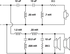
To determine the correct values for our crossover network, we go to page 181 and reference the Crossover Component Selection Guide. The instructions are followed for using the chart, and it is seen that for drivers with an 8 ohm impedance, our crossover values would be a 4.4uF capacitor and a .56mH inductor for both the tweeter and woofer circuits. The closest capacitor value we have is a 4.3uF polypropylene, which is well within range. At this point, our crossover network will look like this:
Notice that the tweeter is connected with reverse polarity. This is normal for all 12 dB per octave filters.
The Crossover Component Selection Guide, as with all crossover formulas, assumes that the crossover network is terminated with a purely resistive load, but a loudspeaker is not even close to being purely resistive! Due to voice coil inductance, the impedance is constantly rising with frequency. To remedy this, a simple capacitor and resistor impedance equalizer called a Zobel network is placed across the positive and negative leads of the woofer. The Zobel is not usually necessary with a tweeter network, so we will design one for our Morel woofer using this formula:
R=1.25 X Re
C=Le/R2
C = Capacitor value in farads
R = Resistor value in ohms
Re = DC resistance of voice coil in ohms
Le = Voice coil inductance in henries

The Morel woofer has a DC resistance of 5.2 ohms and a voice coil inductance of .35mH or .00035 henries. So our Zobel network works out to be .0000129 farads or 12.9uF cap in series with a 6.5 ohm resistor. In practice these values are approximate, and you may want to experiment, particularly with the value of C.
If the driver’s DC resistance or voice coil inductance is unknown, just use the nominal impedance for the value of R (8 ohm driver, use an 8 ohm resistor). The value of C for woofers is generally between 10uF and 50uF. For 5-1/4″ to 8″ woofers, try 10-20uF. 10″ to 12″ woofers, 20-25uF. 15″ to 18″ woofers, 30-50uF. Using this criteria for our Morel woofer, our Zobel would be a 15uF capacitor in series with an 8 ohm resistor. Pretty close to our calculated values!
To prove the effectiveness of a Zobel network, we ran an impedance sweep from 20 to 20 KHz with and without the Zobel network in place, using the LMS audio analyzer. As can be seen on the graph, the Morel MW 162’s free air impedance starts to rise at 400 Hz reaching 12 ohms at 3 KHz (our crossover point), and rising to 33 ohms at 20 KHz. With the Zobel in place (15uF + 8 ohm resistor) the impedance only varies 1.5 ohms from 100 Hz to 20 KHz! Clearly the Zobel network is very effective at flattening the impedance rise. It is also interesting to note that the large impedance peak at 55 Hz is the free air resonance, or Fs, of the Morel woofer.
To complete our crossover design, we must match the output level of the tweeter to the woofer’s. The Morel MDT 10 is rated at 90 dB 1W/1m, while the MW 162 woofer is rated at only 84 dB 1W/1m. The simple solution to this mismatch is to include an L-pad attenuator in our tweeter circuit. This will allow attenuation while maintaining a constant impedance. For our example we will be using two resistors to form a fixed L-type attenuator. The values were calculated using a formula in The Loudspeaker Design Cookbook by Vance Dickason (#500-036). Our final crossover network will now look like this:

Crossover Construction
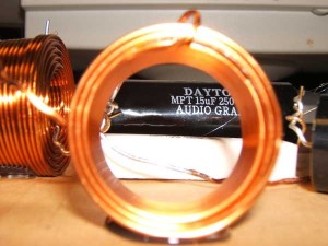
To complete the project, we just need to mount and solder the components to a 2-way, PC board (#260-120). For the highest quality signal transfer, we will use 14 gauge air core inductors and polypropylene capacitors.
When placing more than one inductor on a PC board, always mount them at 90ø angles to each other and try to keep them at least 2 inches apart to avoid inductive coupling. For the same reason, the crossover should be mounted a reasonable distance from the woofer magnet structure. When the crossover is completed, all of the components should be glued to the PC board using epoxy or hot glue (inductors can be quite heavy, requiring epoxy). Once the crossovers are complete and mounted inside the enclosure, we can hook up the drivers and enjoy our work!
One important last word on the crossover, since the tweeter is placed physically ahead of the woofer on a flat baffle, the drivers may now be acoustically out of phase with each other due to time delay. Angling the speaker cabinet back about 6ø will help time align the drivers, thus putting them back in-phase. Also, reversing the tweeter’s polarity may work. Experiment with different combinations of speaker angle and/or tweeter polarity then determine what sounds the best. Getting the phase right will actually eliminate a deep “null” or hole in the frequency response centered on the crossover frequency.
Recommended Reading
This primer was intended to show you the steps required to build a two-way system without the need for expensive measurement equipment. We tried to be as in-depth as possible without getting into too much complex theory. To gain much more valuable information on the subject of loudspeaker drivers, cabinet construction, and crossover design, we highly recommend the following books and publications:
Woofer Selection Guide
The Woofer Selection Guide is intended to help you select the correct woofer for your application. For quick comparison, woofers can be sorted by size, power handling or any other specification by simply clicking on the appropriate column. Many woofers can be used in sealed or vented applications, though there is a trade off between enclosure size and bass extension.
The enclosure volumes and F3s are based on BassBox “optimum” calculations and should be used only as a guide. The enclosure volume of any driver can vary greatly, depending on a variety of factors that are determined by the goals of your particular system. Example: a woofer used in a smaller than optimum vented box is often preferred for high-output, high-power applications. Conversely, a larger than optimum vented box can be used to achieve maximum low-frequency extension but will reduce power handling. Also, by damping the enclosure (particularly in a sealed box) the recommended enclosure size can be reduced up to 25%.
Building A Crossover
Often, one of the most daunting tasks that the beginning speaker-builder faces is building a crossover from scratch. It is easy enough to look at and understand a printed crossover schematic, but it is an altogether different matter to actually build it out of real components. It is a little trickier than it at first seems, and often even seeing a picture of someone’s completed crossover doesn’t really help that much. I remember spending hours trying to figure out where to put all of the different components and not take up half my enclosure!
Since the DIY community is built on the contributions of many people, you will find a wide variety of different ways that a crossover schematic is drawn. Everybody seems to use different software or method for hand writing his or her circuit. Some show each driver with its own completely separate circuit, some branch off in different directions from the same input, and some show grounding points instead of complete circuit paths. Once you practice by looking at a few different types and seeing how they relate, it becomes fairly easy to translate from one type of schematic to the other.
Also, let me mention that many of the following tips and methods work best for parallel crossovers. These are the most common crossovers that you see, and can be identified by sharing the same input for each driver section. Each has its own “branch” of the circuit, and is essentially independent of the other(s). Physically laying out a series crossover is similar, but conceptualizing from the written schematic is more difficult.
The Subject
In this article, we are going to focus our energies on one specific crossover design, that from the Dr. K’s MTM design. This is a two-way crossover, but is fairly complex and uses a decent number of components. A two-way crossover is somewhat easier to work with, and makes a much better illustration of the basic principles.
Breaking Down the Schematic
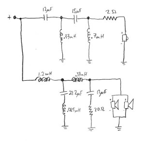
For me to best visualize how a crossover will physically lay out, I prefer to convert it into the type of schematic that shows all the negative connections as grounds. (I usually just do this mentally, but for a complicated crossover, it doesn’t hurt to sketch it out.) *see drawing #1
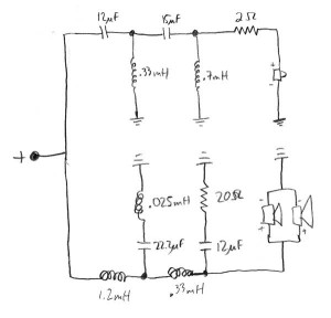
Next, I mentally “flip” the lower portion of the crossover so that all of the grounding points are facing towards each other. *see drawing #2
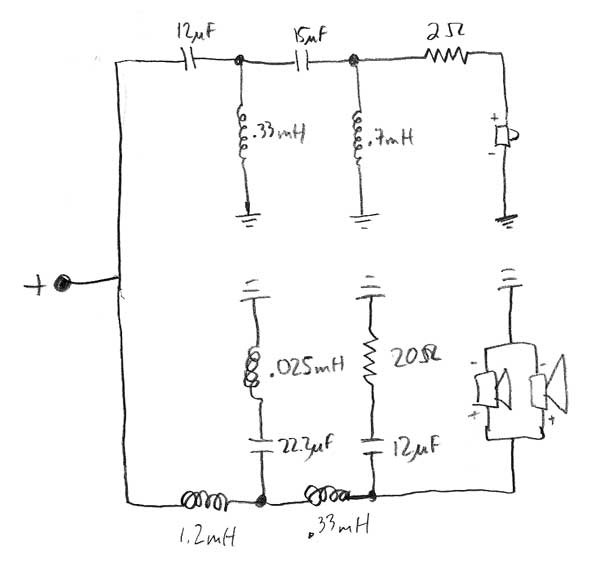
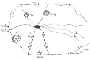
Now, we can start to see that there is some degree of physical organization showing up in the schematic. To take it as far as we can on paper, I’m going to start to replace some of the symbols with drawings, and tie together the grounding points, which are all shared. I haven’t drastically changed the component layout, but rather just made all the ground nodes come together to a common point. I then added the input, tweeter, and woofer + and – wires to the drawing.
*see drawing 3
Schematic
Drawing 1
Drawing 2
Drawing 3
Components
Inductor Placement
Condensing the Layout
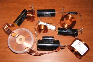
Going back to the crossover at hand, I will begin to condense the layout, keeping in mind the inductor placement factors as above. Carefully bend and arrange the components so that they are close together, but that all connections stay intact. Without too much rearranging, I was able to condense the crossover size to about 6″ by 8″. *see layout #1
This is getting to a reasonable size, and is probably small enough for most applications. In the event that you needed the crossover smaller still, the next thing to look at would be adding a third dimension to the layout. Consider placing capacitors on top of inductors, or resistors on top of capacitors. Once you get into the third dimension, the crossover building quickly becomes almost an artistic, sculptural endeavor. * see layout #2
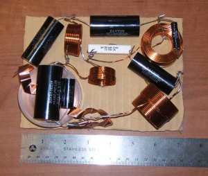
On this final condensed crossover, the board size is 5″ by 7″. Of course, as inductor placement becomes closer and closer, we begin to have to compromise on the inductive coupling issue, but that is just one more compromise that must be made as the builder.
Layout 1
Layout 2

Make the Board
To secure the crossover components, any type of thin, non-magnetic plate will work. Typically, people cut them from 1/4″ plywood or some other sort of manufactured wood product. I’ve seen people use pieces of laminate flooring, where one section can provide enough material for several crossovers. For the cheap or lazy type like myself, you could even use heavy cardboard– gasp! (Hey, glue sticks to it well, it is easy to make holes for wire ties, and you can trim the corners if you need it to fit into a tight space. Don’t knock it ’til you try it!) Cut your board material to size, and place the components on it to get a rough idea if everything will work.
Start Mounting
I like to secure most of the components to the board with hot melt glue. Ideally, one should probably use Silicone or some other high-temp adhesive, but for smallish home speakers, it is much quicker using hot-melt, and I have never had a problem with components coming off. Of course, if I was making the crossover for a high-power pro sound application, then I would probably not use hot-melt glue– but I wouldn’t use cardboard in that case either!
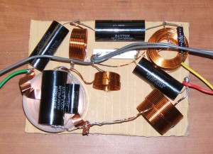
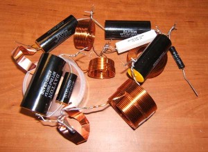
Larger inductors should usually have a wire tie or two on them in addition to the hot-melt glue, but it depends on their orientation and construction. Most small components will remain in place fine with just hot-melt glue. When I use silicone, I wire tie each component, primarily to hold it in place while the silicone is curing. *see image 1
Image 1
Solder
After the board is totally laid out, it is time to go back and start soldering all of the connections. I usually spend a minute neatening up the connections and making sure that no wires are touching that shouldn’t. Due to the large amounts of copper that you will be soldering, you need to have a decently high-powered soldering iron. 25 watts is the bare minimum, but 40 or 50 watts really works best.
The thicker the component lead wires, the longer you’ll need to hold the iron to the joint to heat it up. It takes a bit of practice learn how long it takes to heat the average joint. Extreme overheating can cause damage to components, so if you are having troubles, consider using a heat sink for protection. Again, this is where it is important to have a hot enough iron, if your iron is not hot enough you will have to hold the iron on the joint too long.
Once the joints are all soldered, add your lead wires, solder them in place, and then trim up any stray component leads. At this point, you’re done!